for pedalboards
Reflex
In developmentRelay loop switching for pedalboards, driven by a MIDI/footswitch controller. In development.
Reflex has two parts that work together but are separate: a controller (footswitches and MIDI) that decides what should be on, and relay loop boards that actually switch your pedals in and out of the audio path.
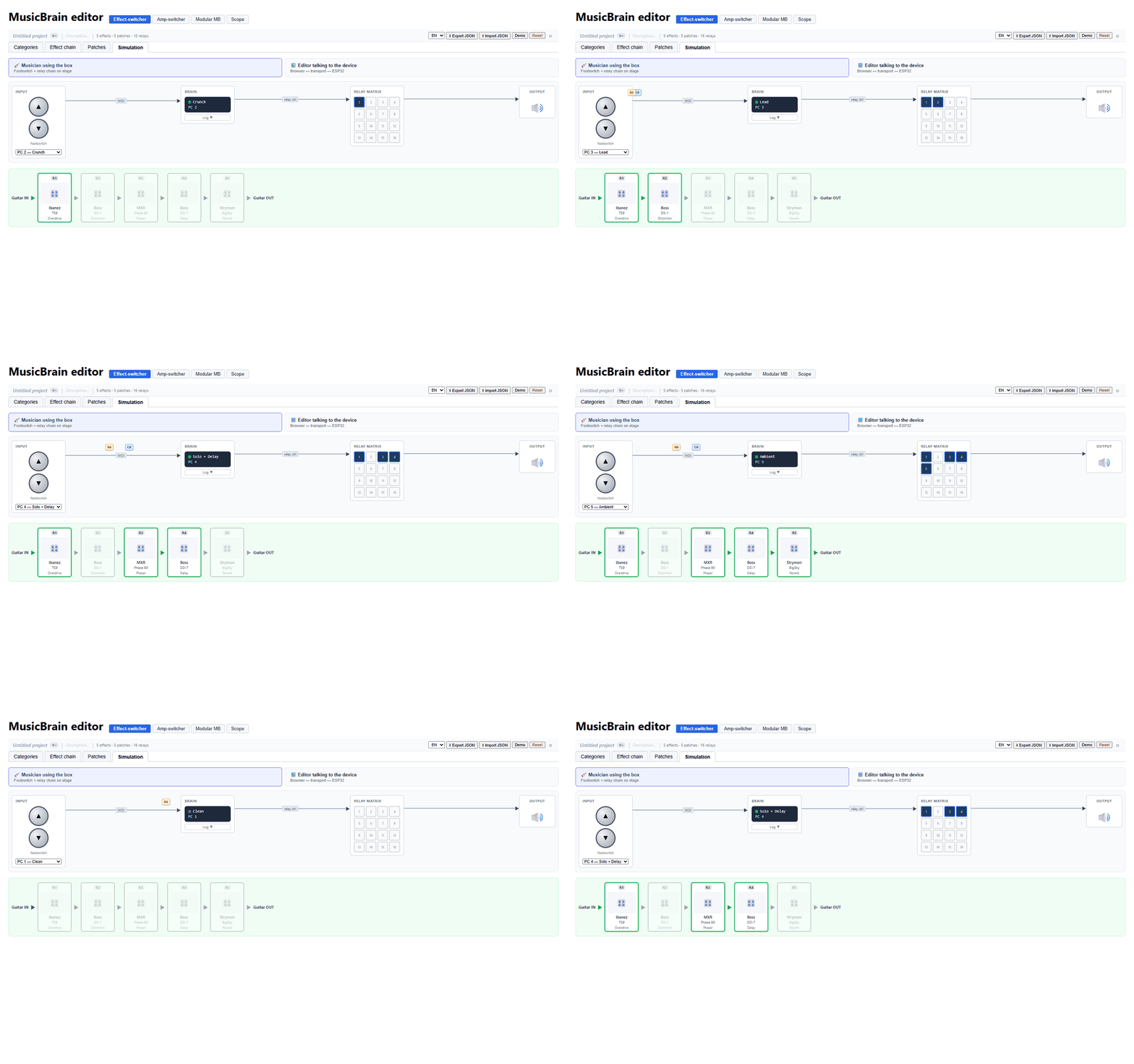
The offline editor lets you build a pedal chain and patches, and simulates MIDI and relay states — it visualizes the switching, it does not emulate the sound of your pedals. Firmware implementations and hardware designs exist (see the Reflex releases); they are not a production-ready build, and hardware status is listed per board. Reflex does not use the Cortex USB workflow.
Specs
| Loop boards | gswitch-loop8 / loop8sh: relay loops (v0.1 designs) |
|---|---|
| Controller (design) | 8 footswitches with RGB rings, per-switch OLED labels |
| Connectivity (design) | MIDI DIN, USB, 2x expression pedal |
| Editor | Offline chain editor with MIDI/relay-state simulation |
Components
Reflex — Brain
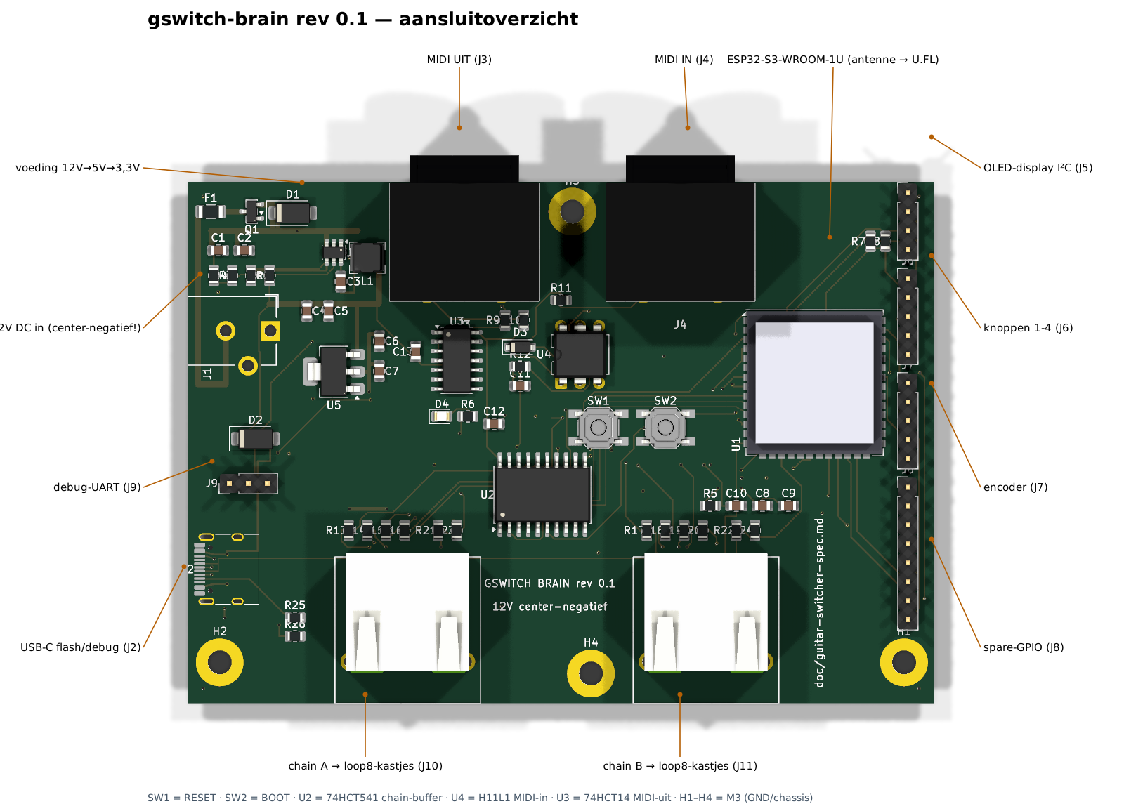
v0.1The brain is the control centre of the switching system. An ESP32-S3 module runs the show: it reads the footswitches and the encoder, drives the OLED display, speaks MIDI on the two DIN sockets, and — after a first firmware flash over USB-C — updates itself over WiFi. The loop boards hang off a deliberately simple control chain. Two shielded RJ45 ports (chain A and B) carry clock, data, latch and enable as buffered 5 V logic, plus the 12 V supply, so each hop in the chain is a single patch cable — but note it is not Ethernet: pin 4 carries 12 V. A return line (DATA_RET) comes back from the far end of the chain, which lets the brain count the connected loop boards at start-up and verify every switching command bit by bit. The enable line is failsafe by design: if the brain loses power or resets, every relay in the chain drops out and all loops fall back to true bypass, so the guitar signal keeps flowing no matter what. Audio ground and control ground are kept strictly separate to keep switching noise out of the signal path.
Board v0.1
Connectors (10)
| J9 · debug-UART | 1→DBG_TX 2→DBG_RX 3→GND |
| J2 · USB-C flash/debug | A1→GND A4→VBUS A5→CC1 A6→USB_DP A7→USB_DM A8→— A9→VBUS A12→GND B1→GND B4→VBUS B5→CC2 B6→USB_DP B7→USB_DM B8→— B9→VBUS B12→GND SH→GND SH→GND SH→GND SH→GND |
| J3 · MIDI UIT | E→GND E→GND 1→— 2→GND 3→— 4→MOUT4 5→MOUT5 |
| J4 · MIDI IN | E→GND E→GND 1→— 2→— 3→— 4→MIN4 5→MIN5 |
| J5 · OLED-display I²C | 1→GND 2→+3V3 3→SCL 4→SDA |
| J6 · knoppen 1-4 | 1→BTN1 2→BTN2 3→BTN3 4→BTN4 5→GND |
| J7 · encoder | 1→ENC_A 2→GND 3→ENC_B 4→ENC_SW 5→GND |
| J8 · spare-GPIO | 1→+3V3 2→GND 3→SPARE1 4→SPARE2 5→SPARE3 6→SPARE4 7→SPARE5 8→SPARE6 |
| J10 · chain A → loop8-kastjes | SH→GND SH→GND 1→A_CLKJ 2→GND 3→A_DATAJ 4→+12V 5→GND 6→A_DRETJ 7→A_LATCHJ 8→A_ENJ |
| J11 · chain B → loop8-kastjes | SH→GND SH→GND 1→B_CLKJ 2→GND 3→B_DATAJ 4→+12V 5→GND 6→B_DRETJ 7→B_LATCHJ 8→B_ENJ |
Reflex — Loop8
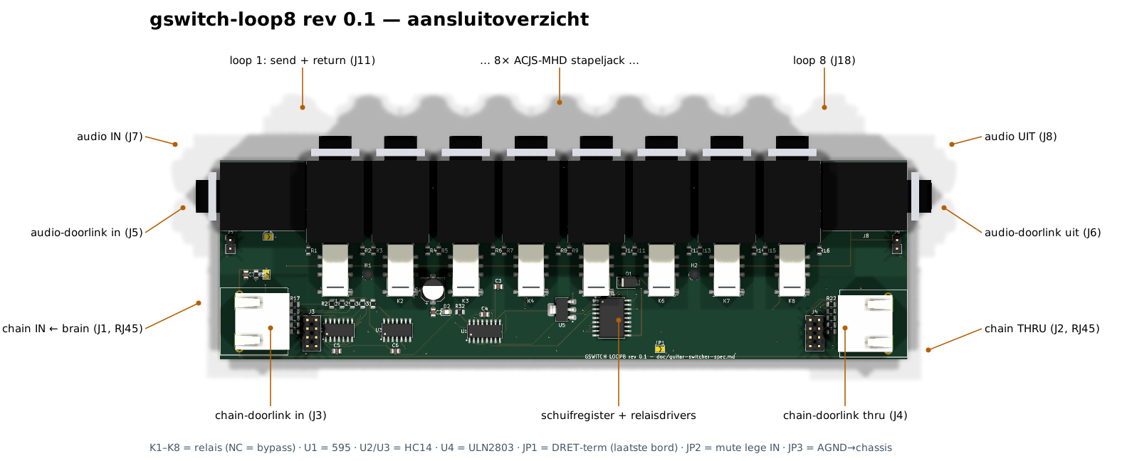
v0.1An eight-loop true-bypass audio switcher. Each loop pairs one DPDT signal relay with a stacked jack: send on top, return underneath. With the relay at rest the signal flows through the normally-closed contacts — true bypass, even with the power off. Energising a relay lifts the signal out through the send jack, through your pedal, and back in on the return. Empty loops take care of themselves: the return jack's switching contact bridges send to return when no plug is inserted, so an unused loop passes the signal untouched. Audio enters on one short edge and leaves on the other. Control arrives over RJ45 (chain in), is re-buffered on the board, and is passed on to the next board (chain thru). For a 16-loop enclosure with two boards, the link stays internal: a short flat cable between the 2×4 link headers carries the control signals and the 12 V supply, and a small screened wire between the audio-link pads takes the audio from the first board's output straight to the second board's input — the two inner jacks are simply left unfitted. Three solder jumpers configure the rest: chain termination (closed on the last board only), muting of an unplugged input, and the single star point that ties audio ground to the chassis — one per enclosure.
Board v0.1
Connectors (10)
| J11 · loop 1: send + return | 1→AGND 2→AGND 3→SEND1 4→AGND 5→AGND 6→RET1 7→AGND 8→AGND 9→— 10→AGND 11→AGND 12→SEND1 |
| J18 · loop 8 | 1→AGND 2→AGND 3→SEND8 4→AGND 5→AGND 6→RET8 7→AGND 8→AGND 9→— 10→AGND 11→AGND 12→SEND8 |
| J7 · audio IN | T→N0 R→AGND S→AGND TN→INTN RN→AGND SN→AGND |
| J5 · audio-doorlink in | 1→N0 2→AGND |
| J1 · chain IN ← brain | SH→CHASSIS SH→CHASSIS 1→CLK_J 2→GND 3→DATA_J 4→+12V 5→GND 6→DRET_J 7→LATCH_J 8→EN_J |
| J8 · audio UIT | T→N8 R→AGND S→AGND TN→— RN→AGND SN→AGND |
| J6 · audio-doorlink uit | 1→N8 2→AGND |
| J2 · chain THRU | SH→CHASSIS SH→CHASSIS 1→CLK_T 2→GND 3→SER_T 4→+12V 5→GND 6→DRETT_J 7→LATCH_T 8→EN_T |
| J3 · chain-doorlink in | 1→CLK_J 2→GND 3→DATA_J 4→+12V 5→GND 6→DRET_J 7→LATCH_J 8→EN_J |
| J4 · chain-doorlink thru | 1→CLK_T 2→GND 3→SER_T 4→+12V 5→GND 6→DRETT_J 7→LATCH_T 8→EN_T |
gswitch-loop8sh
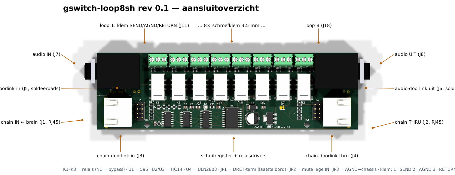
v0.1The compact wired-install variant of the loop8, built for rigs where the effect loops are hard-wired rather than patched. The eight stacked jack pairs make way for a row of eight 3-pole screw terminals (send – shield/audio ground – return), which shrinks the board to 150 × 44 mm and keeps it low enough for flat enclosures. The audio input and output remain real 6.35 mm jacks, and the RJ45 control chain, the internal link header and audio-link pads, and the solder jumpers are identical to the loop8, so both variants mix freely in one chain. One thing screw terminals cannot do is normalling: there is no switching contact, so an empty loop does not bridge itself. Leave unused loops disabled (a relay at rest is still true bypass) or put a short wire between the send and return terminals of that loop. Everything else — relays, failsafe behaviour, separated audio and control grounds — behaves exactly like the bigger board.
Board v0.1
Connectors (10)
| J11 · loop 1: klem SEND/AGND/RETURN | 1→SEND1 2→AGND 3→RET1 |
| J18 · loop 8 | 1→SEND8 2→AGND 3→RET8 |
| J7 · audio IN | T→N0 R→AGND S→AGND TN→INTN RN→AGND SN→AGND |
| J5 · audio-doorlink in | 1→N0 2→AGND |
| J1 · chain IN ← brain | SH→CHASSIS SH→CHASSIS 1→CLK_J 2→GND 3→DATA_J 4→+12V 5→GND 6→DRET_J 7→LATCH_J 8→EN_J |
| J8 · audio UIT | T→N8 R→AGND S→AGND TN→— RN→AGND SN→AGND |
| J6 · audio-doorlink uit | 1→N8 2→AGND |
| J2 · chain THRU | SH→CHASSIS SH→CHASSIS 1→CLK_T 2→GND 3→SER_T 4→+12V 5→GND 6→DRETT_J 7→LATCH_T 8→EN_T |
| J3 · chain-doorlink in | 1→CLK_J 2→GND 3→DATA_J 4→+12V 5→GND 6→DRET_J 7→LATCH_J 8→EN_J |
| J4 · chain-doorlink thru | 1→CLK_T 2→GND 3→SER_T 4→+12V 5→GND 6→DRETT_J 7→LATCH_T 8→EN_T |
Reflex editor
v0.2.0Browser-based editor for the Reflex effect switcher. You lay out your pedalboard as a signal chain, group sounds into patches, and try the whole rig in a built-in simulation before touching any hardware: the on-screen footswitch sends real MIDI program-change bytes through the same parser that runs in the firmware. Everything works offline in the browser; a JSON export carries the configuration to the device.
Software v0.2.0
Releases
- reflex v0.1 · 2026-07-14 · beta
- guitar-switcher v0.1 · 2026-07-11 · dev