Component
Reflex — Brain
v0.1
The brain is the control centre of the switching system. An ESP32-S3 module runs the show: it reads the footswitches and the encoder, drives the OLED display, speaks MIDI on the two DIN sockets, and — after a first firmware flash over USB-C — updates itself over WiFi.
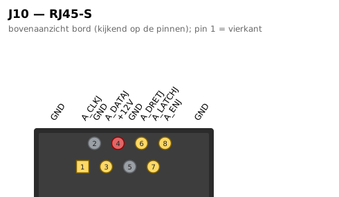
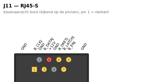
The loop boards hang off a deliberately simple control chain. Two shielded RJ45 ports (chain A and B) carry clock, data, latch and enable as buffered 5 V logic, plus the 12 V supply, so each hop in the chain is a single patch cable — but note it is not Ethernet: pin 4 carries 12 V. A return line (DATA_RET) comes back from the far end of the chain, which lets the brain count the connected loop boards at start-up and verify every switching command bit by bit.
The enable line is failsafe by design: if the brain loses power or resets, every relay in the chain drops out and all loops fall back to true bypass, so the guitar signal keeps flowing no matter what. Audio ground and control ground are kept strictly separate to keep switching noise out of the signal path.
Used in
Board v0.1
pinned by reflex v0.1 · beta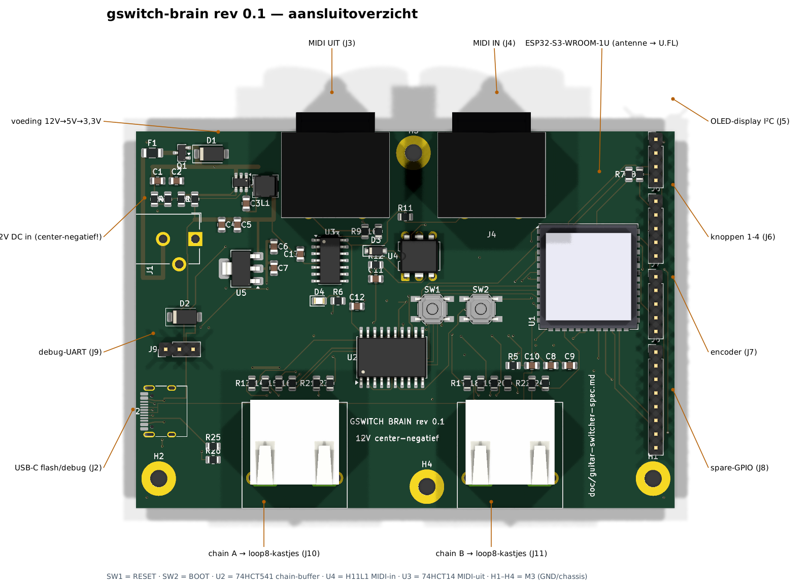
Connectors (10)
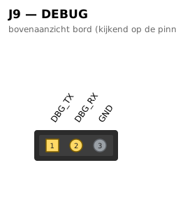
| J9 · debug-UART | 1→DBG_TX 2→DBG_RX 3→GND |
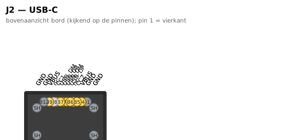
| J2 · USB-C flash/debug | A1→GND A4→VBUS A5→CC1 A6→USB_DP A7→USB_DM A8→— A9→VBUS A12→GND B1→GND B4→VBUS B5→CC2 B6→USB_DP B7→USB_DM B8→— B9→VBUS B12→GND SH→GND SH→GND SH→GND SH→GND |
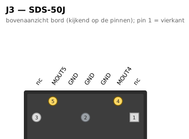
| J3 · MIDI UIT | E→GND E→GND 1→— 2→GND 3→— 4→MOUT4 5→MOUT5 |
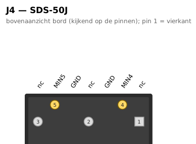
| J4 · MIDI IN | E→GND E→GND 1→— 2→— 3→— 4→MIN4 5→MIN5 |
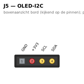
| J5 · OLED-display I²C | 1→GND 2→+3V3 3→SCL 4→SDA |
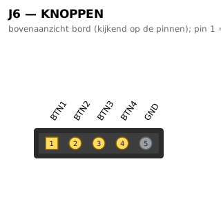
| J6 · knoppen 1-4 | 1→BTN1 2→BTN2 3→BTN3 4→BTN4 5→GND |
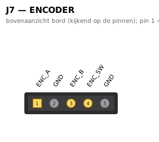
| J7 · encoder | 1→ENC_A 2→GND 3→ENC_B 4→ENC_SW 5→GND |
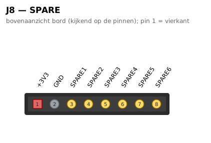
| J8 · spare-GPIO | 1→+3V3 2→GND 3→SPARE1 4→SPARE2 5→SPARE3 6→SPARE4 7→SPARE5 8→SPARE6 |
| J10 · chain A → loop8-kastjes | SH→GND SH→GND 1→A_CLKJ 2→GND 3→A_DATAJ 4→+12V 5→GND 6→A_DRETJ 7→A_LATCHJ 8→A_ENJ |
| J11 · chain B → loop8-kastjes | SH→GND SH→GND 1→B_CLKJ 2→GND 3→B_DATAJ 4→+12V 5→GND 6→B_DRETJ 7→B_LATCHJ 8→B_ENJ |
Pinout diagrams (10)
Aansluitoverzicht
gswitch-brain rev 0.1 — aansluitoverzicht