Component
Reflex — Loop8
v0.1
An eight-loop true-bypass audio switcher. Each loop pairs one DPDT signal relay with a stacked jack: send on top, return underneath. With the relay at rest the signal flows through the normally-closed contacts — true bypass, even with the power off. Energising a relay lifts the signal out through the send jack, through your pedal, and back in on the return. Empty loops take care of themselves: the return jack's switching contact bridges send to return when no plug is inserted, so an unused loop passes the signal untouched.
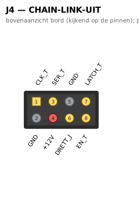
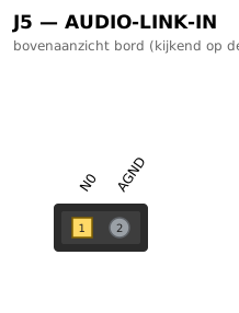
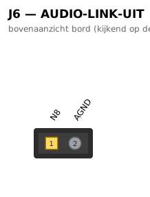
Audio enters on one short edge and leaves on the other. Control arrives over RJ45 (chain in), is re-buffered on the board, and is passed on to the next board (chain thru). For a 16-loop enclosure with two boards, the link stays internal: a short flat cable between the 2×4 link headers carries the control signals and the 12 V supply, and a small screened wire between the audio-link pads takes the audio from the first board's output straight to the second board's input — the two inner jacks are simply left unfitted.
Three solder jumpers configure the rest: chain termination (closed on the last board only), muting of an unplugged input, and the single star point that ties audio ground to the chassis — one per enclosure.
Used in
Board v0.1
pinned by reflex v0.1 · beta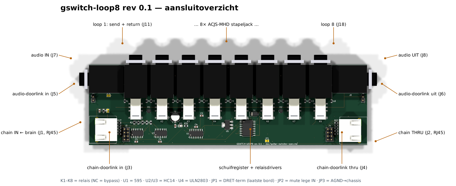
Connectors (10)
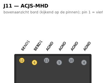
| J11 · loop 1: send + return | 1→AGND 2→AGND 3→SEND1 4→AGND 5→AGND 6→RET1 7→AGND 8→AGND 9→— 10→AGND 11→AGND 12→SEND1 |
| J18 · loop 8 | 1→AGND 2→AGND 3→SEND8 4→AGND 5→AGND 6→RET8 7→AGND 8→AGND 9→— 10→AGND 11→AGND 12→SEND8 |
| J7 · audio IN | T→N0 R→AGND S→AGND TN→INTN RN→AGND SN→AGND |
| J5 · audio-doorlink in | 1→N0 2→AGND |
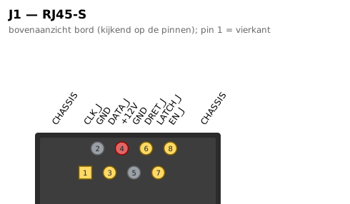
| J1 · chain IN ← brain | SH→CHASSIS SH→CHASSIS 1→CLK_J 2→GND 3→DATA_J 4→+12V 5→GND 6→DRET_J 7→LATCH_J 8→EN_J |
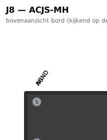
| J8 · audio UIT | T→N8 R→AGND S→AGND TN→— RN→AGND SN→AGND |
| J6 · audio-doorlink uit | 1→N8 2→AGND |
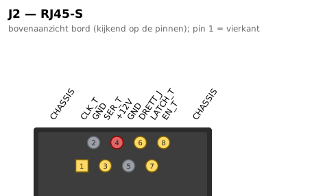
| J2 · chain THRU | SH→CHASSIS SH→CHASSIS 1→CLK_T 2→GND 3→SER_T 4→+12V 5→GND 6→DRETT_J 7→LATCH_T 8→EN_T |
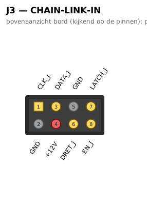
| J3 · chain-doorlink in | 1→CLK_J 2→GND 3→DATA_J 4→+12V 5→GND 6→DRET_J 7→LATCH_J 8→EN_J |
| J4 · chain-doorlink thru | 1→CLK_T 2→GND 3→SER_T 4→+12V 5→GND 6→DRETT_J 7→LATCH_T 8→EN_T |
Pinout diagrams (16)
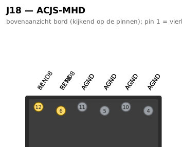
Aansluitoverzicht
gswitch-loop8 rev 0.1 — aansluitoverzicht