Component
gswitch-loop8sh
v0.1
The compact wired-install variant of the loop8, built for rigs where the effect loops are hard-wired rather than patched. The eight stacked jack pairs make way for a row of eight 3-pole screw terminals (send – shield/audio ground – return), which shrinks the board to 150 × 44 mm and keeps it low enough for flat enclosures. The audio input and output remain real 6.35 mm jacks, and the RJ45 control chain, the internal link header and audio-link pads, and the solder jumpers are identical to the loop8, so both variants mix freely in one chain.
One thing screw terminals cannot do is normalling: there is no switching contact, so an empty loop does not bridge itself. Leave unused loops disabled (a relay at rest is still true bypass) or put a short wire between the send and return terminals of that loop.
Everything else — relays, failsafe behaviour, separated audio and control grounds — behaves exactly like the bigger board.
Used in
Board v0.1
pinned by reflex v0.1 · beta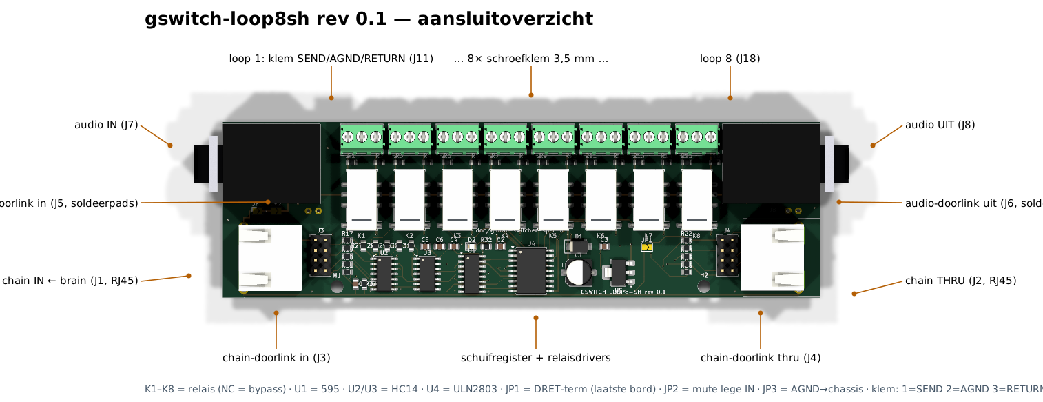
Connectors (10)
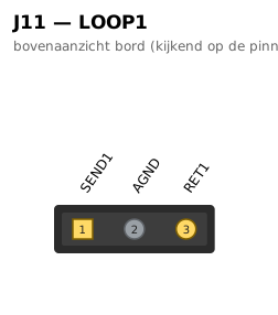
| J11 · loop 1: klem SEND/AGND/RETURN | 1→SEND1 2→AGND 3→RET1 |
| J18 · loop 8 | 1→SEND8 2→AGND 3→RET8 |
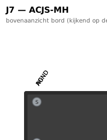
| J7 · audio IN | T→N0 R→AGND S→AGND TN→INTN RN→AGND SN→AGND |
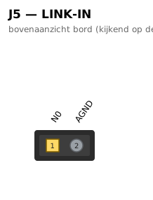
| J5 · audio-doorlink in | 1→N0 2→AGND |
| J1 · chain IN ← brain | SH→CHASSIS SH→CHASSIS 1→CLK_J 2→GND 3→DATA_J 4→+12V 5→GND 6→DRET_J 7→LATCH_J 8→EN_J |
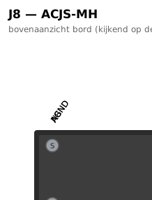
| J8 · audio UIT | T→N8 R→AGND S→AGND TN→— RN→AGND SN→AGND |
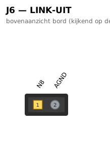
| J6 · audio-doorlink uit | 1→N8 2→AGND |
| J2 · chain THRU | SH→CHASSIS SH→CHASSIS 1→CLK_T 2→GND 3→SER_T 4→+12V 5→GND 6→DRETT_J 7→LATCH_T 8→EN_T |
| J3 · chain-doorlink in | 1→CLK_J 2→GND 3→DATA_J 4→+12V 5→GND 6→DRET_J 7→LATCH_J 8→EN_J |
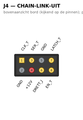
| J4 · chain-doorlink thru | 1→CLK_T 2→GND 3→SER_T 4→+12V 5→GND 6→DRETT_J 7→LATCH_T 8→EN_T |
Pinout diagrams (9)
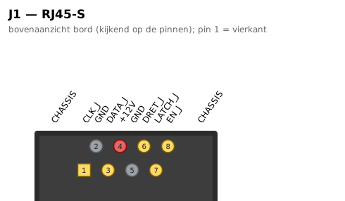
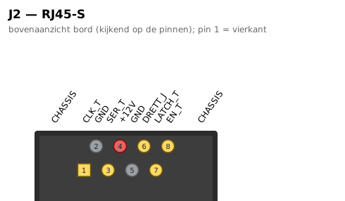
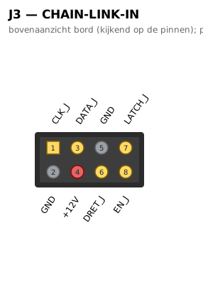
Aansluitoverzicht
gswitch-loop8sh rev 0.1 — aansluitoverzicht